


In meiner Jugend habe ich ganz klassisch mit dem Flugmodellbau begonnen. Erst ein Dandy, dann der Amigo und schließlich Motorflug mit der Taxi.
Nach meiner Schulzeit habe ich viele Jahre ausgesetzt und dann wieder angefangen mit einem Hotliner, doch der Reiz war nicht mehr da … etwas neues musste her.
Jahrelang hatte ich in meiner Jugend von Modellhubschraubern geträumt und jetzt waren sie für mich bezahlbar.
Also den Hotliner verkauft und klassisch mit den Hubis angefangen: Koaxial mit Ikarus Piccolo, dann der ECO 8, ein Zoom 400 und ein Logo 10.
![]()
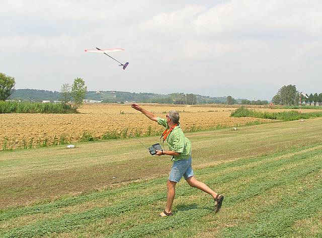
Wenn ich mich mal sportlich betätigen 🙂 möchte schmeiße ich meinen SAL in die Luft
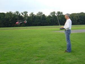
Aber eigentlich bin ich immer bei den Mikado Helis geblieben und fliege heute einen Logo 400.
![]()
Mittlerweile habe ich meine gute alte Multiplex MC 3030 durch eine Multiplex Cockpit SX 9 Anlage mit Telemetrie ersetzt. Tolles Teil!
Die Möglichkeiten der Telemietrie haben mich richtig angefixt und so habe ich gleich begonnen mich mit dem Thema zu beschäftigen.
Als erstes habe ich meinen „Lastenträger“, eine DJI 550 Hexakopter mit einem AnySense – Telemetrie Modul ausgestattet. Coole Sache, ist aber noch die V1.1 Version und kann daher leider keine Alarme an meine Multiplex Cockpit SX 9 übertragen (Details kann man im Link des nächsten Absatzes lesen). Da muss ich noch was basteln 😉
Der Multiplex Sensor Bus (MSB)
(Richtig gute Beschreibung bei Microcontroller.net von cyblord)
Ich habe dann mal angefangen auf Basis eines Teensy 3.2 (Arduino kompatibles all in one Board) einen eigenen MSB Sensor Emulator, MSB Sensor bzw. MSB Sensor Logger zu erstellen. Dabei herausgekommen ist …
Der FrSKY MSB Protokollwandler
Damit können – quasi beliebig viele – FrSKY Sensoren per FrSKY Bus an meinem Protokollwandler angeschlossen werden, welcher wiederum als Sensor an einem Multiplex Empfänger mit MSB angeschlossen wird. Der Protokollwandler pollt – fragt also periodisch die FrSKY Sensoren am Bus ab – und gleichzeitig emuliert er alle entsprechenden Sensoren auf Seiten des MSB und senden die entsprechenden Informationen an den Empfänger.
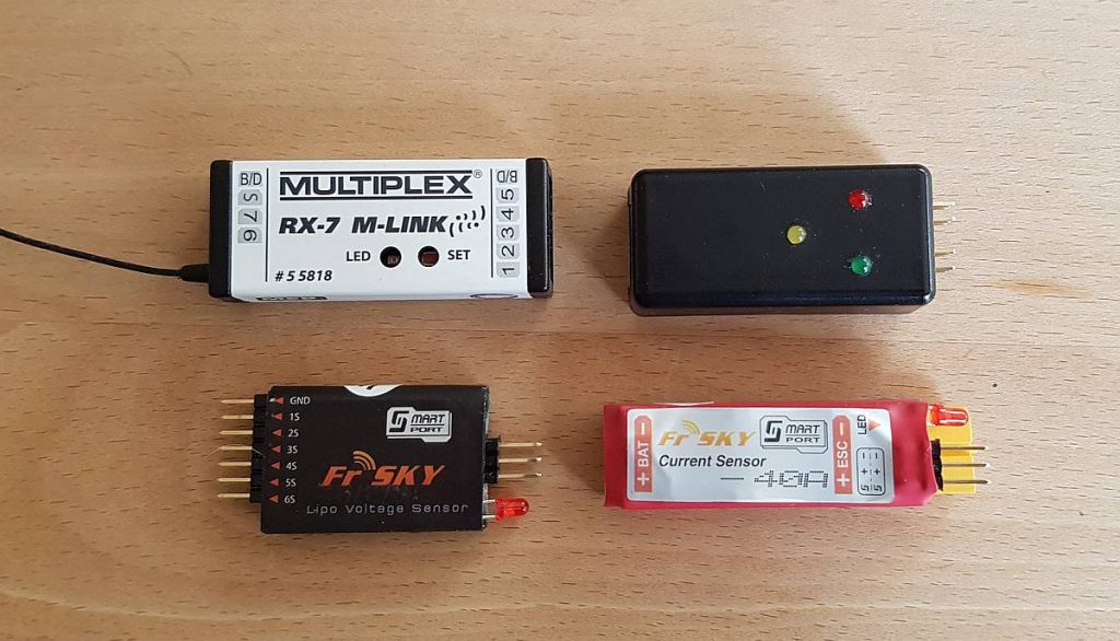
Hier mal ein Bild der verwendeten Komponenten ohne Verkabelung.
Falls jemand so etwas nachbauen will hier einige Codezeilen der entsprechenden Arduino Entwicklungsumgebung
/*
* FryLink Telemetry Converter Includes
*
* from Burkhard Vogt, Muenster, Westfalia, Germany
*
* These are the defines for FrSky S.Port
*
*/
#define FrSkyPIdAnz 26
const byte FrSkyPId[] =
{
0x00, // Physical ID 1 – Vario2 (altimeter high precision)
0xA1, // Physical ID 2 – FLVSS Lipo sensor (can be sent with one or two cell voltages)
0x22, // Physical ID 3 – FAS-40S current sensor
0x83, // Physical ID 4 – GPS / altimeter (normal precision)
0xE4, // Physical ID 5 – RPM
0x45, // Physical ID 6 – SP2UART(Host)
0xC6, // Physical ID 7 – SPUART(Remote)
0x67, // Physical ID 8 –
0x48, // Physical ID 9 –
0xE9, // Physical ID 10 –
0x6A, // Physical ID 11 –
0xCB, // Physical ID 12 –
0xAC, // Physical ID 13 –
0x0D, // Physical ID 14 –
0x8E, // Physical ID 15 –
0x2F, // Physical ID 16 –
0xD0, // Physical ID 17 –
0x71, // Physical ID 18 –
0xF2, // Physical ID 19 –
0x53, // Physical ID 20 –
0x34, // Physical ID 21 –
0x95, // Physical ID 22 –
0x16, // Physical ID 23 –
0xB7, // Physical ID 24 – Receiver quality ?
0x98, // Physical ID 25 – Fuel ?
0x39, // Physical ID 26 –
0xBA, // Physical ID 27 – Timer ?
0x1B // Physical ID 28 –
};
/*
* FryLink Telemetry Converter
*
* from Burkhard Vogt, Munster, Westfalia, Germany
*
* Idea and sources from Jochen Tuchbreiter
*
* Connections:
* Vin – Input (Bus) power by RX of MPX
* Gnd
* A1 – Signal wire MLINK
* A3 – Signal LED (green)
* A6 – Setup LED (yellow)
* A10 – Signal wire FrSky
* A12 – Signal LED (red)
*/
#include <EEPROM.h>
struct Sensor
{
unsigned short uTypID;
short iMin;
short iMax;
byte bAlert;
short iValue;
byte bClass;
byte bBuzz;
unsigned long ulMsec;
}
SensDef[16];
// #define DEBUG
// #define DEBUG_SETUP
// #define DEBUG_MLINK
// #define DEBUG_FRSKY
// Serial interfaces used
#define DebugSerial Serial
#define MLinkSerial Serial1
#define FrSkySerial Serial2
#define MLinkSerial_C1 UART0_C1
#define MLinkSerial_C3 UART0_C3
#define FrSkySerial_C1 UART1_C1
#define FrSkySerial_C3 UART1_C3
// Some defines for the serial communication
#define FRSKY_POLLING 10 // Time between two polling requests
#define MLINK_DELAY 3 // Time between request and answer
// Some global variables for the LEDs
const byte MLinkLED = 3; // The green MLink LED
const byte SetupLED = 6; // The yellow Setup LED
const byte FrSkyLED = 12; // The red FrSky LED
// Some global variables for the setup
#define SETUP_BEGIN 0xBA
#define SETUP_READ 0xBB
#define SETUP_WRITE 0xBC
#define SETUP_END 0xBE
#define SETUP_ESC 0xBF
// Write sensor definitions
void WriteSetting ( byte bIdx )
{
#ifdef DEBUG_SETUP
DebugSerial.print ( „Write setting to EEPROM for “ );
DebugSerial.println ( bIdx );
#endif
byte bI, *bBytes = (byte *) &SensDef[bIdx];
for ( bI=0; bI<8; bI++ )
{
#ifdef DEBUG_SETUP
DebugSerial.print ( bBytes[bI], HEX );
DebugSerial.print ( “ “ );
#endif
if ( EEPROM[bIdx*8+bI] != bBytes[bI] ) EEPROM[bIdx*8+bI] = bBytes[bI];
}
#ifdef DEBUG_SETUP
DebugSerial.println ();
#endif
}
// Sets the right class for given TypID
void SetSensClass ( byte bIdx )
{
switch ( SensDef[bIdx].uTypID )
{
case 0x0200:
SensDef[bIdx].bClass = 2; // Current
break;
default:
SensDef[bIdx].bClass = 1; // Voltage
}
return;
}
// Read sensor definitions
void ReadSettings ()
{
byte bI, bIdx = 0;
#ifdef DEBUG_SETUP
DebugSerial.println ( „Read setting from EEPROM“ );
#endif
for ( bI=0; bI<16; bI++)
{
byte bK, *bBytes;
bBytes = (byte *) &SensDef[bI];
#ifdef DEBUG_SETUP
DebugSerial.print ( bIdx );
DebugSerial.print ( “ – “ );
#endif
for ( bK=0; bK<8; bK++ )
{
bBytes[bK] = EEPROM[bIdx++];
#ifdef DEBUG_SETUP
DebugSerial.print ( bBytes[bK], HEX );
DebugSerial.print ( “ “ );
#endif
SetSensClass ( bI );
SensDef[bI].iValue = 0x8000;
SensDef[bI].bBuzz = 0;
SensDef[bI].ulMsec = 0;
}
#ifdef DEBUG_SETUP
DebugSerial.println ();
#endif
}
}
// Startup function to initialize serial communication,
// global settings, some led blinking and so on
void setup()
{
#ifdef DEBUG
while ( !DebugSerial ) { ; }
DebugSerial.println ( „Program and funktion setup start“ );
#endif
// Setup the pin states
pinMode ( MLinkLED, OUTPUT );
pinMode ( FrSkyLED, OUTPUT );
pinMode ( SetupLED, OUTPUT );
// Setup the serial communication
DebugSerial.begin ( 9600 );
MLinkSerial.begin ( 38400 );
FrSkySerial.begin ( 57600, SERIAL_8N1_RXINV_TXINV );
MLinkSerial_C1 |= 0x20 + 0x80; // Single wire mode
#ifdef DEBUG_SETUP
DebugSerial.println ( „Set MLink single wire mode“ );
#endif
FrSkySerial_C1 |= 0x20 + 0x80; // Single wire mode
#ifdef DEBUG_SETUP
DebugSerial.println ( „Set FrSky single wire mode“ );
DebugSerial.println ( „Set FrSky TX/RX invert“ );
#endif
MLinkSerial.clear();
FrSkySerial.clear();
byte bI;
ReadSettings ();
byte bCmd = 0;
for ( bI=0; bI<12; bI++)
{
byte bLed = bI % 3;
digitalWrite ( MLinkLED, bLed == 0 ? HIGH : LOW );
digitalWrite ( SetupLED, bLed == 1 ? HIGH : LOW );
digitalWrite ( FrSkyLED, bLed == 2 ? HIGH : LOW );
bCmd = MLinkSerial.read();
if ( bCmd == SETUP_BEGIN ) break;
delay ( 500 );
}
digitalWrite ( FrSkyLED, LOW );
#ifdef DEBUG_SETUP
DebugSerial.println ( „End of wait for setup start“ );
#endif
if ( bI < 12 && bCmd == SETUP_BEGIN )
{
int nOnOff = HIGH;
digitalWrite ( MLinkLED, HIGH );
digitalWrite ( FrSkyLED, LOW );
DebugSerial.println ( „Setup loop start“ );
while ( bCmd != SETUP_ESC )
{
switch ( bCmd )
{
case SETUP_BEGIN:
{
#ifdef DEBUG_SETUP
DebugSerial.println ( „Write info message to MLink serial“ );
#endif
MLinkSerial_C3 |= 0x20;
MLinkSerial.write ( SETUP_BEGIN );
MLinkSerial.print ( „FryLink Version 1.0 from Burkhard R. Vogt, Muenster, Germany“ );
MLinkSerial.write ( SETUP_END );
MLinkSerial.flush (); // make sure send is complete
MLinkSerial_C3 ^= 0x20;
MLinkSerial.clear(); // and clear the pipe
break;
}
case SETUP_READ: // The PC program will get the EEPROM infos
{
#ifdef DEBUG_SETUP
DebugSerial.println ( „Write setting to MLink serial“ );
#endif
MLinkSerial_C3 |= 0x20;
MLinkSerial.write ( SETUP_READ );
for ( bI=0; bI<16; bI++)
{
byte bK, *bBytes = (byte *) &SensDef[bI];
#ifdef DEBUG_SETUP
DebugSerial.print ( bI );
DebugSerial.print ( “ – “ );
#endif
for ( bK=0; bK<8; bK++ )
{
#ifdef DEBUG_SETUP
DebugSerial.print ( bBytes[bK], HEX );
DebugSerial.print ( “ “ );
#endif
MLinkSerial.write ( bBytes[bK] );
}
#ifdef DEBUG_SETUP
DebugSerial.println ();
#endif
}
MLinkSerial.write ( SETUP_END );
MLinkSerial.flush (); // make sure send is complete
MLinkSerial_C3 ^= 0x20;
MLinkSerial.clear(); // and clear the pipe
break;
}
case SETUP_WRITE: // The PC program sends one new sensor info
{
#ifdef DEBUG_SETUP
DebugSerial.println ( „Read setting from MLink serial“ );
#endif
byte bBytes[10];
for ( bI=0; bI<10; bI++ )
{
bBytes[bI] = MLinkSerial.read();
#ifdef DEBUG_SETUP
DebugSerial.print ( bBytes[bI], HEX );
DebugSerial.print ( “ “ );
#endif
}
#ifdef DEBUG_SETUP
DebugSerial.println ();
#endif
if ( bBytes[9] == SETUP_END )
{
byte bIdx = bBytes[0]; // Only for better reading …
#ifdef DEBUG_SETUP
DebugSerial.println ( „New settings OK“ );
#endif
memcpy ( &SensDef[bIdx], bBytes + 1, 8 );
SetSensClass ( bIdx );
WriteSetting ( bIdx );
}
break;
}
}
bCmd = MLinkSerial.read ();
digitalWrite ( SetupLED, nOnOff );
nOnOff = nOnOff == HIGH ? LOW : HIGH;
delay ( 200 );
}
digitalWrite ( SetupLED, LOW );
#ifdef DEBUG_SETUP
DebugSerial.println ( „Setup loop end“ );
#endif
}
// Delete all data in pipes …
MLinkSerial.clear();
FrSkySerial.clear();
digitalWrite ( MLinkLED, LOW );
digitalWrite ( FrSkyLED, LOW );
for ( bI=0; bI<(FrSkyPIdAnz*5); bI++ )
{
HandleFrSky ();
}
#ifdef DEBUG
DebugSerial.println ( „Function loop should start ;-)“ );
#endif
}
// Some global variables for the FrSky serial handling
unsigned long ulFrSkyMsec = 0;
byte bFrSkySId = 0;
byte bFrSkyRead = 0;
byte bFrSkyByte[8];
// Saves the value read from FrSky in sensor struct for MLink request
void SaveValue ( unsigned int uTypID, short iValue )
{
for ( byte bI = 0; bI < 16; bI++ )
{
if ( SensDef[bI].uTypID == uTypID )
{
SensDef[bI].iValue = iValue;
if ( SensDef[bI].bAlert )
{
if ( iValue < SensDef[bI].iMin )
{
SensDef[bI].bBuzz = 1;
}
else
{
if ( iValue > SensDef[bI].iMax )
{
SensDef[bI].bBuzz = 1;
}
else
{
SensDef[bI].bBuzz = 0;
}
}
}
SensDef[bI].ulMsec = millis ();
#ifdef DEBUG_FRSKY
DebugSerial.print ( „FrSky input value saved as “ );
DebugSerial.println ( bI );
#endif
}
}
return;
}
// Function to handle the FrSky serial communication
void HandleFrSky ()
{
if ( FrSkySerial.available() )
{
// Set LED on when data reading …
if ( ! bFrSkyRead ) digitalWrite ( FrSkyLED, HIGH );
bFrSkyByte[bFrSkyRead] = FrSkySerial.read();
// Check for FrSky stuffing spezial char
if ( bFrSkyByte[bFrSkyRead] == 0x7D )
{
while ( ! FrSkySerial.available() ) { ; }
// Read the „real“ value
bFrSkyByte[bFrSkyRead] = FrSkySerial.read() | 0x20;
}
#ifdef DEBUG_FRSKY
DebugSerial.print ( bFrSkyByte[bFrSkyRead], HEX );
DebugSerial.print ( “ “ );
#endif
if ( bFrSkyRead++ < 7 ) return;
#ifdef DEBUG_FRSKY
DebugSerial.println ();
#endif
// Parameter set is complete
if ( bFrSkyByte[0] == 0x10 )
{
unsigned short uTypID = ( bFrSkyByte[2] << 8 ) + bFrSkyByte[1];
#ifdef DEBUG_FRSKY
DebugSerial.print ( „TypID: “ );
DebugSerial.println ( uTypID, HEX );
#endif
switch ( uTypID )
{
case 0x0110: // vario | 0.01m/s | int32
break;
case 0x0200: // current | 0.01A | uint32
{
unsigned long uValue;
memcpy ( &uValue, bFrSkyByte + 3, 4 );
#ifdef DEBUG_FRSKY
DebugSerial.print ( „Current 0.1A: “ );
DebugSerial.println ( uValue / 10 );
#endif
SaveValue ( uTypID, uValue / 10 );
break;
}
case 0x0210: // voltage | 0.01V | uint32
{
unsigned long uValue;
memcpy ( &uValue, bFrSkyByte + 3, 4 );
#ifdef DEBUG_FRSKY
DebugSerial.print ( „Voltage 0.1V: “ );
DebugSerial.println ( uValue / 10 );
#endif
SaveValue ( uTypID, uValue / 10 );
break;
}
case 0x0300: // voltage | 0.01V | uint32
{
unsigned long uValue;
memcpy ( &uValue, bFrSkyByte + 3, 4 );
byte bCell = uValue & 0x0F; // First cell of two
uValue >>= 4;
byte bCells = uValue & 0x0F; // Num of cells
uValue >>= 4;
#ifdef DEBUG_FRSKY
DebugSerial.print ( „Voltage Cell “ );
DebugSerial.print ( bCell );
DebugSerial.print ( “ 0.1V: “ );
DebugSerial.println ( ( uValue & 0x0FFF ) / 50 );
#endif
SaveValue ( uTypID + bCell, ( uValue & 0x0FFF ) / 50 );
bCell ++;
if ( bCell < bCells )
{
uValue >>= 12;
#ifdef DEBUG_FRSKY
DebugSerial.print ( „Voltage Cell “ );
DebugSerial.print ( bCell );
DebugSerial.print ( “ 0.1V: “ );
DebugSerial.println ( ( uValue & 0x0FFF ) / 50 );
#endif
SaveValue ( uTypID + bCell, ( uValue & 0x0FFF ) / 50 );
}
break;
}
case 0x0500: // RPM | 1rpm | uint32
break;
case 0x0600: // capacity used | 1mah | uint32
break;
case 0x0610: // altitude | 1m | int32
break;
case 0x0830: // gps speed | 1km/h | uint32
break;
#ifdef DEBUG_FRSKY
default:
DebugSerial.println ( „Wrong TypID!“ );
#endif
}
}
else
{
#ifdef DEBUG_FRSKY
DebugSerial.println ( „Wrong byte input!“ );
#endif
}
bFrSkyRead = 0;
}
if ( ulFrSkyMsec < ( millis () – FRSKY_POLLING ) )
{
ulFrSkyMsec = millis ();
FrSkySerial_C3 |= 32;
FrSkySerial.write( 0x7E );
FrSkySerial.write( FrSkyPId[bFrSkySId] );
FrSkySerial.flush(); // make shure send is complete
FrSkySerial_C3 ^= 32;
#ifdef DEBUG_FRSKY
DebugSerial.print ( „Sending FrSky request “ );
DebugSerial.print ( bFrSkySID );
DebugSerial.print ( “ “ );
DebugSerial.print ( FrSkyPID[bFrSkySID], HEX );
DebugSerial.println ();
#endif
if ( bFrSkySId++ > FrSkyPIdAnz ) bFrSkySId = 0;
bFrSkyRead = 0;
digitalWrite ( FrSkyLED, LOW );
}
}
// Function to handle the MLink serial communication
void HandleMLink ()
{
byte bMLinkID = MLinkSerial.read();
if ( bMLinkID < 16 )
{
#ifdef DEBUG_MLINK
DebugSerial.print ( bMLinkID, HEX );
DebugSerial.print ( “ “ );
#endif
delay ( 3 );
// For secure, if another sensor uses the same ID
if ( ! MLinkSerial.available() )
{
// Is this sensor ID defined?
if ( SensDef[bMLinkID].uTypID )
{
digitalWrite ( MLinkLED, HIGH );
byte bRet = ( bMLinkID << 4 ) + SensDef[bMLinkID].bClass;
short iVal;
// Check if the last response is to old !
if ( SensDef[bMLinkID].ulMsec < ( millis () – FRSKY_POLLING * 100 ) )
{
iVal = 0x8000;
}
else
{
iVal = SensDef[bMLinkID].iValue * 2;
if ( SensDef[bMLinkID].bAlert ) iVal += SensDef[bMLinkID].bBuzz;
}
MLinkSerial_C3 |= 0x20;
MLinkSerial.write ( bRet ); // send sensor address and typ
MLinkSerial.write ( lowByte ( iVal ) );
MLinkSerial.write ( highByte ( iVal ) );
MLinkSerial.flush (); // make sure send is complete
MLinkSerial_C3 ^= 0x20;
#ifdef DEBUG_MLINK
DebugSerial.print ( „MLink response“ );
#endif
digitalWrite ( MLinkLED, LOW );
}
}
else
{
byte bReq = 0;
while ( MLinkSerial.available() )
{
#ifdef DEBUG_MLINK
DebugSerial.print ( MLinkSerial.read(), HEX );
DebugSerial.print ( “ “ );
#else
MLinkSerial.read();
#endif
if ( bReq++ > 2 ) break;
}
}
}
else
{
#ifdef DEBUG_MLINK
DebugSerial.print ( „!- “ );
DebugSerial.print ( bMLinkID, HEX );
DebugSerial.print ( “ “ );
#endif
while ( MLinkSerial.available() )
{
#ifdef DEBUG_MLINK
DebugSerial.print ( MLinkSerial.read(), HEX );
DebugSerial.print ( “ “ );
#else
MLinkSerial.read();
#endif
}
}
#ifdef DEBUG_MLINK
DebugSerial.println ();
#endif
}
// The endless loop
void loop ()
{
while ( MLinkSerial.available() ) { HandleMLink (); }
HandleFrSky (); // Time for the FrSky S.Port
}
Der MSB GPS Sensor
Hätte ich mir auch fertig von Multiplex kaufen können; kann ja jeder 😉
Da ich mich im Rahmen der Entwickllung eines XCSoar Varios auf Basis eines Kobo Ebook Readers schon mal mit GPS Empfängern beschäftigt hatte lagen die Bauteile quasi auf meinem Basteltisch.
Nach der Initialisierung wird die aktuelle Standposition und Höhe ermittelt, so dass nach dem Start (Geschwindigkeit größer 5km/h) folgende Werte übertragen werden können
- Geschwindigkeit (dafür habe ich es eigentlich gebaut)
- Höhe
- Entfernung von der Standposition
- Satelliten in Sicht (werden empfangen)
- … und jeweils die Maximalwerte
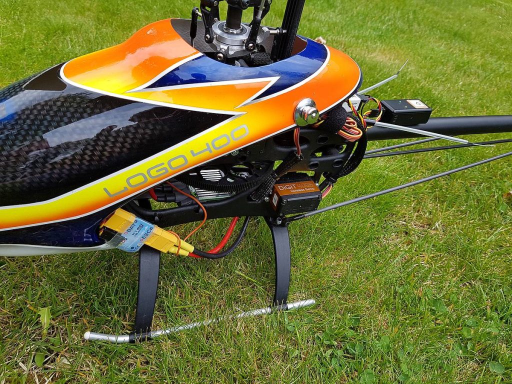
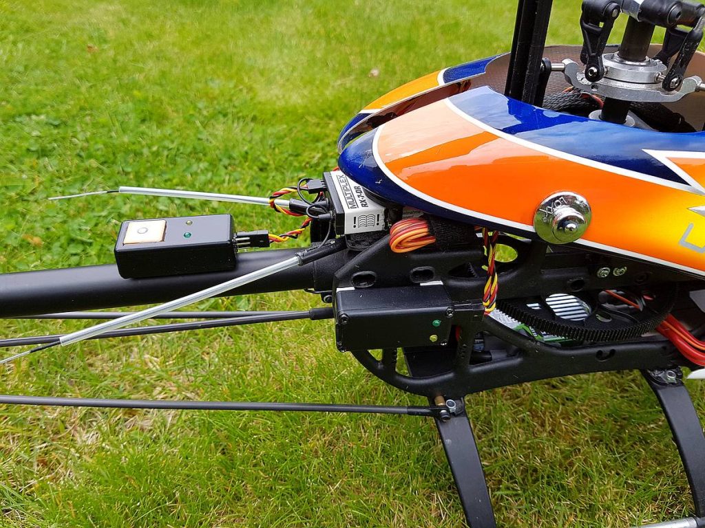
Der Sensor auf dem Heckausleger mit GPS-Modul PA6H von Exp-Tech. Gut zu erkennen auch der ebenfalls angeschlossene UniSens-E Strom- und Spannungs- und Drehzahlsensor von SM Modellbau.
Falls jemand so etwas nachbauen will hier einige Codezeilen der entsprechenden Arduino Entwicklungsumgebung
/*
* Multiplex GPS Sensor
*
* from Burkhard Vogt, Muenster, Westfalia, Germany
*
* Connections:
* Vin – Input (Bus) power by RX of MPX
* Gnd
* A1 – Serial wire MPX
* A3 – Signal LED (green)
* A6 – GPS LED (red)
* A10 – TX GPS
*/
#include <EEPROM.h>
#include <string.h>
#include <ctype.h>
#include <math.h>
const double M_RO = 180.0 / M_PI;
#define DebSerial Serial
#define MpxSerial Serial1
#define GpsSerial Serial2
#define MpxSerial_C1 UART0_C1
#define MpxSerial_C3 UART0_C3
// Some defines for the serial communication
#define MPX_DELAY 0 // Time between request and answer
// Some define for the start position
#define POS_DELAY 20 // Position sentence to wait for start
#define MID_DELAY 5 // Position sentence to middel (must lower than wait)
// the minimal speed to start
#define MIN_SPEED 5.0 // Minimum start speed
// Some global variables for the LEDs
const byte GpsLED = 3; // The yellow GPS LED
const byte MpxLED = 6; // The green Mpx LED
/* Sensor definitions
Types are:
– 01 – Speed
– 02 – Hight
– 03 – Distance
– 04 – Sattelites in view
– 05 – Max. Speed
– 06 – Max. Hight
– 07 – Max. Distance
– 08 – Max. Sattelites in view */
struct Sensor
{
byte bTyp;
byte bAlert;
short iValue;
byte bClass;
byte bBuzz;
}
SensDef[16];
byte SensRef[8]; // Reference for the real values (types)
// #define DEBUG
// #define DEBUG_SETUP
// #define DEBUG_MPX
// #define DEBUG_GPS
// Startadresse der Sensorausgabe
#define SADR 7
void setup()
{
#ifdef DEBUG
while ( ! DebSerial ) { ; }
DebSerial.begin ( 9600 );
DebSerial.println ( „Program and funktion setup start“ );
#endif
for ( byte bI=0; bI<10; bI++ )
{
SensDef[bI].bTyp = 0;
}
SensDef[SADR+0].bTyp = 1; // Speed
SensDef[SADR+0].bAlert = 0; // No alarm
SensDef[SADR+0].iValue = 0x8000; // No value
SensDef[SADR+0].bClass = 4; // Speed 0,1km/h
SensDef[SADR+0].bBuzz = 0; // No buzzer
SensDef[SADR+1].bTyp = 2; // Hight
SensDef[SADR+1].bAlert = 0; // No alarm
SensDef[SADR+1].iValue = 0x8000; // No value
SensDef[SADR+1].bClass = 8; // Hight 1m
SensDef[SADR+1].bBuzz = 0; // No buzzer
SensDef[SADR+2].bTyp = 3; // Distance
SensDef[SADR+2].bAlert = 0; // No alarm
SensDef[SADR+2].iValue = 0x8000; // No value
SensDef[SADR+2].bClass = 8; // short distance 1m
SensDef[SADR+2].bBuzz = 0; // No buzzer
SensDef[SADR+3].bTyp = 4; // Sattelites
SensDef[SADR+3].bAlert = 0; // No alarm
SensDef[SADR+3].iValue = 0x8000; // No value
SensDef[SADR+3].bClass = 15; // Num. Sattelites
SensDef[SADR+3].bBuzz = 0; // No buzzer
SensDef[SADR+4].bTyp = 5; // Speed
SensDef[SADR+4].bAlert = 0; // No alarm
SensDef[SADR+4].iValue = 0x8000; // No value
SensDef[SADR+4].bClass = 4; // Speed 0,1km/h
SensDef[SADR+4].bBuzz = 0; // No buzzer
SensDef[SADR+5].bTyp = 8; // Distance
SensDef[SADR+5].bAlert = 0; // No alarm
SensDef[SADR+5].iValue = 0x8000; // No value
SensDef[SADR+5].bClass = 8; // Short distance 1m
SensDef[SADR+5].bBuzz = 0; // No buzzer
for ( byte bI=0; bI<8; bI++ )
{
SensRef[bI] = 0;
}
for ( byte bI=0; bI<16; bI++ )
{
if ( SensDef[bI].bTyp ) SensRef[SensDef[bI].bTyp-1] = bI + 1;
}
// Setup the pin states
pinMode ( MpxLED, OUTPUT );
pinMode ( GpsLED, OUTPUT );
// Setup the serial communication
MpxSerial.begin ( 38400 );
GpsSerial.begin ( 9600 );
MpxSerial_C1 |= 0x20 + 0x80; // Single wire mode
for ( byte bI=0; bI<6; bI++)
{
byte bLed = bI % 2;
digitalWrite ( MpxLED, bLed == 0 ? HIGH : LOW );
digitalWrite ( GpsLED, bLed == 1 ? HIGH : LOW );
delay ( 500 );
}
digitalWrite ( MpxLED, LOW );
digitalWrite ( GpsLED, LOW );
MpxSerial.clear();
GpsSerial.clear();
#ifdef DEBUG
DebSerial.println ( „Function loop should start ;-)“ );
#endif
}
char GpsBuf[256];
byte GpsIdx = 0;
static const char Hex[] = „0123456789ABCDEF“;
double GetPos ( char *pStr, byte bLen )
{
char cDeg[4];
byte bI;
for ( bI=0; bI<bLen; bI++ )
{
if ( pStr[bI] == 0 ) return ( 0.0 );
cDeg[bI] = pStr[bI];
}
cDeg[bI] = 0;
double dDeg = atof ( cDeg );
double dMin = atof ( pStr + bLen );
return ( dDeg + dMin / 60.0 );
}
float fHgt, fHgtS = 0.0;
double dLat, dLon, dLatS = 0.0, dLonS = 0.0, dRad;
float fHight, fHightM = 0.0, fSpeed, fSpeedM = 0.0, fDist, fDistM = 0.0;
byte bFix = 0, bSat = 0, bSatM = 0, bVal = 0;
byte bMpxLED = 0;
byte bGpsLED = 0;
byte bPosCnt = 0;
// Function to handle the Mpx serial communication
void HandleMpx ()
{
byte bMLinkID = MpxSerial.read();
if ( bMLinkID < 16 )
{
#ifdef DEBUG_MPX
DebSerial.print ( bMLinkID, HEX );
DebSerial.print ( “ “ );
#endif
delay ( MPX_DELAY );
if ( ! bMLinkID )
{
if ( bMpxLED )
{
digitalWrite ( MpxLED, LOW );
bMpxLED = 0;
}
else
{
digitalWrite ( MpxLED, HIGH );
bMpxLED = 1;
}
}
if ( bMLinkID == 7 )
{
if ( ! bFix || ! bSat || ! bVal || bPosCnt < POS_DELAY )
{
digitalWrite ( MpxLED, LOW );
bMpxLED = 0;
}
}
// For secure, if another sensor uses the same ID
if ( ! MpxSerial.available() )
{
// Is this sensor ID defined?
if ( SensDef[bMLinkID].bTyp )
{
byte bRet = ( bMLinkID << 4 ) + SensDef[bMLinkID].bClass;
short iVal;
if ( bFix && bSat && bVal && bPosCnt >= POS_DELAY )
{
iVal = SensDef[bMLinkID].iValue * 2;
}
else
{
iVal = 0x8000;
}
if ( SensDef[bMLinkID].bAlert ) iVal += SensDef[bMLinkID].bBuzz;
MpxSerial_C3 |= 0x20;
MpxSerial.write ( bRet ); // send sensor address and typ
MpxSerial.write ( lowByte ( iVal ) );
MpxSerial.write ( highByte ( iVal ) );
MpxSerial.flush (); // make sure send is complete
MpxSerial_C3 ^= 0x20;
#ifdef DEBUG_MPX
DebSerial.print ( „MLink response“ );
#endif
}
}
else
{
byte bReq = 0;
while ( MpxSerial.available() )
{
#ifdef DEBUG_MPX
DebSerial.print ( MpxSerial.read(), HEX );
DebSerial.print ( “ “ );
#else
MpxSerial.read();
#endif
if ( bReq++ > 2 ) break;
}
}
}
else
{
#ifdef DEBUG_MPX
DebSerial.print ( „!- “ );
DebSerial.print ( bMLinkID, HEX );
DebSerial.print ( “ “ );
#endif
#ifdef DEBUG_MPX
while ( MpxSerial.available() )
{
DebSerial.print ( MpxSerial.read(), HEX );
DebSerial.print ( “ “ );
}
#else
if ( MpxSerial.available() ) MpxSerial.clear();
#endif
}
#ifdef DEBUG_MPX
DebSerial.println ();
#endif
}
void SaveVal ( byte bTyp, short iVal )
{
if ( ! SensRef[bTyp-1] ) return;
SensDef[SensRef[bTyp-1]-1].iValue = iVal;
}
// Function to handle the GPS serial communication
void HandleGps ()
{
GpsBuf[GpsIdx] = GpsSerial.read();
if ( GpsBuf[GpsIdx] == 255 ) return;
if ( GpsBuf[GpsIdx] == 10 || GpsBuf[GpsIdx] == 13 )
{
if ( GpsIdx > 3 )
{
#ifdef DEBUG_GPS
GpsBuf[GpsIdx+1] = 0;
#endif
if ( GpsBuf[GpsIdx-3] != ‚*‘ ) return; // Wrong format!
byte bI, CRC = 0; // Calculate the CRC and check
for ( bI=1; bI<(GpsIdx-3); bI++ ) CRC = CRC ^ GpsBuf[bI] ;
if ( GpsBuf[GpsIdx-2] != Hex[(CRC & 0xf0) >> 4] ||
GpsBuf[GpsIdx-1] != Hex[(CRC & 0x0f)] ) return;
#ifdef DEBUG_GPS
DebSerial.println ( GpsBuf );
#endif
byte bCmd = 0;
for ( bI=0; bI<2; bI++ )
{
char cCmd[] = { „GPGGA,GPRMC,“ };
byte bK;
for ( bK=0; bK<6; bK++ )
{
if ( GpsBuf[bK+1] != cCmd[bI*6+bK] ) break;
}
if ( bK == 6 )
{
bCmd = bI * 20 + 20;
break;
}
}
if ( bCmd )
{
byte bStart = 7;
byte bParam = 0;
for ( bI=bStart; bI<(GpsIdx-2); bI++ )
{
if ( GpsBuf[bI] == ‚,‘ || GpsBuf[bI] == ‚*‘ )
{
GpsBuf[bI] = 0;
bParam++;
switch ( bCmd + bParam )
{
case 41: if ( bGpsLED )
{
digitalWrite ( GpsLED, LOW );
bGpsLED = 0;
}
else
{
if ( bFix && bSat && bVal )
{
digitalWrite ( GpsLED, HIGH );
bGpsLED = 1;
}
}
break;
case 42: if ( GpsBuf[bStart] == ‚A‘ )
{
bVal = 1;
}
else
{
bVal = 0;
}
break;
case 22:
case 43: dLat = GetPos ( GpsBuf + bStart, 2 );
#ifdef DEBUG_GPS
DebSerial.print ( „Lat “ );
DebSerial.println ( dLat, 4 );
#endif
break;
case 23:
case 44: if ( GpsBuf[bStart] == ‚S‘ ) dLat *= -1.0;
break;
case 24:
case 45: dLon = GetPos ( GpsBuf + bStart, 3 );
#ifdef DEBUG_GPS
DebSerial.print ( „Lon “ );
DebSerial.println ( dLon, 4 );
#endif
break;
case 25:
case 46: if ( GpsBuf[bStart] == ‚W‘ ) dLon *= -1.0;
break;
case 26: bFix = atoi ( GpsBuf + bStart );
break;
case 27: bSat = atoi ( GpsBuf + bStart );
if ( bSat > bSatM ) bSatM = bSat;
SaveVal ( 4, min ( bSat, 10 ) );
SaveVal ( 8, min ( bSatM, 10 ) );
#ifdef DEBUG_GPS
DebSerial.print ( „Sats “ );
DebSerial.println ( bSat );
#endif
break;
case 29: fHgt = atof ( GpsBuf + bStart );
if ( bFix && bSat && bVal && bPosCnt >= POS_DELAY )
{
fHight = fHgt – fHgtS;
if ( fHight > fHightM ) fHightM = fHight;
#ifdef DEBUG_GPS
DebSerial.print ( „Hight “ );
DebSerial.println ( fHight, 1 );
#endif
}
else
{
fHight = 0x8000;
}
SaveVal ( 2, max ( 0, fHight ) );
SaveVal ( 6, fHightM );
break;
case 47: if ( bFix && bSat && bVal && bPosCnt >= POS_DELAY )
{
fSpeed = atof ( GpsBuf + bStart ) * 1.852;
#ifdef DEBUG_GPS
DebSerial.print ( „Speed “ );
DebSerial.println ( fSpeed, 2 );
#endif
if ( fSpeed < MIN_SPEED )
{
fSpeed = 0.0;
}
else
{
if ( fSpeed > fSpeedM ) fSpeedM = fSpeed;
}
}
else
{
fSpeed = 0x8000;
}
SaveVal ( 1, fSpeed * 10 );
SaveVal ( 5, fSpeedM * 10 );
#ifdef DEBUG_GPS
case 21:
case 28:
case 48:
case 49:
break;
default: DebSerial.print ( bCmd + bParam );
DebSerial.print ( „-“ );
DebSerial.println ( GpsBuf+bStart );
#endif
}
if ( bParam > 8 ) break; // No more interesting params …
bStart = bI + 1;
}
}
if ( bFix && bSat && bVal )
{
if ( bPosCnt < POS_DELAY )
{
bPosCnt ++;
if ( bPosCnt > ( POS_DELAY – MID_DELAY ) )
{
#ifdef DEBUG_GPS
DebSerial.print ( „Save start position … “ );
DebSerial.println ( bPosCnt – POS_DELAY + MID_DELAY );
#endif
fHgtS += fHgt / MID_DELAY;
dLatS += dLat / MID_DELAY;
dLonS += dLon / MID_DELAY;
if ( bPosCnt == POS_DELAY )
{
dRad = 111300 * cos ( dLatS / M_RO );
#ifdef DEBUG_GPS
DebSerial.println ( „Startpoint“ );
DebSerial.print ( „Lat “ );
DebSerial.println ( dLatS, 4 );
DebSerial.print ( „Lon “ );
DebSerial.println ( dLonS, 4 );
DebSerial.print ( „Hight “ );
DebSerial.println ( fHgtS, 1 );
DebSerial.print ( „Rad m “ );
DebSerial.println ( dRad, 0 );
#endif
}
}
}
else
{
#ifdef DEBUG_GPS
DebSerial.println ( „Calculate distance“ );
#endif
double dX = ( dLon – dLonS ) * dRad;
double dY = ( dLat – dLatS ) * 111300;
fDist = sqrt ( dX * dX + dY * dY );
if ( fDist <= 2000 )
{
if ( fDist > fDistM ) fDistM = fDist;
}
else
{
fDist = 0x8000;
}
SaveVal ( 3, fDist );
SaveVal ( 7, fDistM );
#ifdef DEBUG_GPS
DebSerial.print ( „Dist “ );
DebSerial.println ( fDist, 2 );
#endif
}
}
}
}
GpsIdx = 0;
}
else
{
if ( GpsBuf[0] == ‚$‘ ) GpsIdx++;
if ( GpsIdx > 255 ) GpsIdx = 0;
}
}
void loop ()
{
if ( MpxSerial.available() ) HandleMpx ();
if ( GpsSerial.available() ) HandleGps ();
}
Der MSB Sensor Logger
Ich wollte erst einen Logger entwickeln den ich direkt in meinen Sender einbaue. Da hatte ich noch meine geliebte MC 3030. Doch hat das drei ganz entscheidende Nachteile:
- Man macht sich Hardwareabhängig!
Es hätte also mit meinem neuen Sender nicht mehr funktioniert … - Aber viel entscheidender: Die Pollingrate!
Also die Anzahl erfasster Sensorwerte während einer Zeiteinheit.
Auf dem MSB Bus werden die Sensoren viel häufiger abgefragt als diese zum Sender übertragen werden. - Verfügbarkeit ist vom Emfang des Senders abhängig
Ich will’s ja nicht herbeireden, aber sollte der Empfänger (Sende- oder Empfangsmodul) oder Empfänger (Sende- oder Empfangsmodul) ausfallen sind die Sensordaten futsch. Natürlich auch der dann ganz interessante Link Quality Indicator (LQI) oder aber auch Strom- und Spannung, welche auf eine Ausfallursache hindeuten könnten.
Also habe ich den Logger so konzipiert, dass er einfach auf dem MSB mitlauscht 😉
Außerdem konnte ich erstmals übern von einer angeschlossenen Micro-SD-Karte zu lesen und zu schreiben.
Der Logger verarbeitet eine Konfigurationsdatei (Minimal Strom- und Spannungswerte) wann das Logging beginnen bzw. beendet werden soll. Anschließend wird nach einer definierten Anzahl von Sensorabfragen geprüft, welche Sensoren und Sensorentypen überhaupt am MSB angeschlossen sind bzw. welche Informationen übertragen werden. Hieraus lässt sich dann die Beschriftung für eine CSV Datei erstellen. Die Datensätze werden anschließend sequensziell – nach Abfrage jeweils aller angeschlossenen Sensoren – in diese Datei geschrieben.
Hier nochmals der GPS Sensor auf dem Heckausleger und der MSB Logger an der rechten Seite. Etwas schwer ist die Micro-SD-Karte auf der linken Seite des MSB Loggers zu erkennen.
Falls jemand so etwas nachbauen wollen hier einige Codezeilen der entsprechenden Arduino Entwicklungsumgebung
/*
* Multiplex Telemetry Display Logger
*
* from Burkhard Vogt, Munster, Westfalia, Germany
*
* Connections:
* Vin – Power by TX (HFM3) of MPX
* Gnd
* A1 – Signal wire MLINK
*
* SD card attached to SPI bus as follows:
* MOSI – pin 11
* MISO – pin 12
* CLK – pin 13
* CS – pin 4
*
* A1 – Signal wire MLINK
* A3 – Signal LED (green)
* A6 – Setup LED (yellow)
*/
#include <SPI.h>
#include <SD.h>
struct SensDef
{
byte bClass;
short iValue;
}
Sensor[16];
char szFileName[13];
// #define DEBUG
// #define DEBUG_FILE
// #define DEBUG_MLINK
// Serial interfaces used
#define Debug Serial
#define MLink Serial1
#define SENS_WAIT 100
const byte GreenLED = 3; // The green LED
const byte YellowLED = 6; // The yellow LED
byte bBuffer[20], bBufIdx = 0;
int iMinA = 20; // Min power to start (1/10A)
int iMinR = 500; // Min rmp to start
char cDeci = ‚,‘; // Decimal in Excel CSV
void setup()
{
// Setup the pin states
pinMode ( GreenLED, OUTPUT );
pinMode ( YellowLED, OUTPUT );
digitalWrite ( GreenLED, HIGH );
digitalWrite ( YellowLED, HIGH );
// For best compatiblity with all SD cards
pinMode ( 4, INPUT_PULLUP );
pinMode ( 10, INPUT_PULLUP );
delay (1); // allow time for both pins to reach 3.3V
#ifdef DEBUG_FILE
Debug.begin ( 9600 );
while ( ! Serial ) {;}
#endif
#ifdef DEBUG_FILE
Debug.print ( „Initializing SD card …“ );
#endif
if ( ! SD.begin ( 4 ) )
{
#ifdef DEBUG_FILE
Debug.println ( “ failed!“ );
#endif
return;
}
#ifdef DEBUG_FILE
Debug.println ( “ done.“ );
#endif
File fRoot = SD.open ( „/“ );
File fEntry;
unsigned int uLastIdx = 0;
while ( fEntry = fRoot.openNextFile () )
{
if ( ! fEntry.isDirectory())
{
if ( strlen ( fEntry.name() ) == 12 )
{
strcpy ( szFileName, fEntry.name() );
if ( ! strncmp ( szFileName, „LOG“, 3 ) &&
! strncmp ( szFileName + 8, „.CSV“, 4 ) )
{
unsigned int uIdx = atoi ( szFileName + 3 );
if ( uLastIdx < uIdx ) uLastIdx = uIdx;
}
}
}
fEntry.close();
}
sprintf ( szFileName, „LOG%05u.CSV“, ++uLastIdx );
#ifdef DEBUG_FILE
Debug.print ( „Filename “ );
Debug.println ( szFileName );
#endif
File SetFile = SD.open ( „SETTINGS.TXT“, FILE_READ );
if ( SetFile )
{
byte bByte;
do
{
bByte = SetFile.read();
if ( bByte == 0 ||
bByte == 0xFF ||
bByte == ‚\n‘ ||
bByte == ‚\r‘ )
{
bBuffer[bBufIdx] = 0;
if ( strlen ( (char *) bBuffer ) )
{
#ifdef DEBUG_FILE
Debug.println ( (char *) bBuffer );
#endif
if ( strncmp ( (char *) bBuffer, „MinA=“, 5 ) == 0 )
{
iMinA = atoi ( (char *) bBuffer + 5 );
#ifdef DEBUG_FILE
Debug.println ( „MinA->“ );
Debug.println ( iMinA );
#endif
}
else if ( strncmp ( (char *) bBuffer, „MinR=“, 5 ) == 0 )
{
iMinR = atoi ( (char *) bBuffer + 5 );
#ifdef DEBUG_FILE
Debug.println ( „MinR->“ );
Debug.println ( iMinR );
#endif
}
else if ( strncmp ( (char *) bBuffer, „Deci=“, 5 ) == 0 )
{
cDeci = bBuffer[5];
if ( cDeci != ‚.‘ || cDeci != ‚,‘ ) cDeci = ‚,‘;
#ifdef DEBUG_FILE
Debug.println ( „Deci“ );
Debug.println ( cDeci );
#endif
}
}
bBufIdx = 0;
}
else
{
if ( bBufIdx < 18 )
{
bBuffer[bBufIdx++] = bByte;
}
}
} while ( bByte != 0xFF );
SetFile.close ();
}
else
{
File SetFile = SD.open ( „SETTINGS.TXT“, FILE_WRITE );
if ( SetFile )
{
Debug.println ( „MinA=20“ );
Debug.println ( „MinR=500“ );
Debug.println ( „Deci=,“ );
SetFile.close ();
}
}
bBufIdx = 0;
MLink.begin ( 38400 );
MLink.clear ();
digitalWrite ( GreenLED, LOW );
}
byte bLastIdx = 0;
byte bWriteSet = 0;
byte bToggle = 0;
unsigned int uWait = 0;
unsigned long ulMillis;
void ToggleLED ( byte LEDon, byte LEDoff )
{
if ( bToggle )
{
bToggle = 0;
digitalWrite ( LEDon, LOW );
}
else
{
bToggle = 1;
digitalWrite ( LEDon, HIGH );
}
digitalWrite ( LEDoff, LOW );
}
void HandleOutput ( void )
{
if ( uWait > SENS_WAIT )
{
if ( bWriteSet )
{
ToggleLED ( GreenLED, YellowLED );
File LogFile = SD.open ( szFileName, FILE_WRITE );
if ( LogFile )
{
char szOutput[12];
unsigned long ulDM = ( millis () – ulMillis ) / 100; // 1/10 sek
unsigned int uiSM = ulDM % 10;
ulDM /= 10;
unsigned int uiSec = ulDM % 60;
ulDM /= 60;
unsigned int uiMin = ulDM % 60;
ulDM /= 60;
sprintf ( szOutput, „%02lu:%02u:%02u%c%01u;“, ulDM, uiMin, uiSec, cDeci, uiSM );
LogFile.print ( szOutput );
for ( byte bI=0; bI<16; bI++ )
{
switch ( Sensor[bI].bClass )
{
case 1:
case 2:
case 3:
case 4:
case 6:
case 7:
case 13:
sprintf ( szOutput, „%i%c%i;“, Sensor[bI].iValue / 10, cDeci, Sensor[bI].iValue % 10 );
LogFile.print ( szOutput );
break;
case 5:
if ( Sensor[bI].iValue < 0 )
{
LogFile.print ( abs ( Sensor[bI].iValue * 10 ) );
}
else
{
LogFile.print ( Sensor[bI].iValue * 100 );
}
LogFile.print ( „;“ );
break;
case 8:
case 9:
case 10:
case 11:
case 12:
case 14:
case 15:
LogFile.print ( Sensor[bI].iValue );
LogFile.print ( „;“ );
}
}
LogFile.println ();
LogFile.close ();
}
}
else
{
ToggleLED ( YellowLED, GreenLED );
}
}
else
{
if ( uWait == SENS_WAIT )
{
ToggleLED ( GreenLED, YellowLED );
ulMillis = millis ();
File LogFile = SD.open ( szFileName, FILE_WRITE );
if ( LogFile )
{
LogFile.print ( „Zeit (1/10s);“ );
for ( byte bI=0; bI<16; bI++ )
{
switch ( Sensor[bI].bClass )
{
case 1: LogFile.print ( „Spannung (V);“ ); break;
case 2: LogFile.print ( „Strom (A);“ ); break;
case 3: LogFile.print ( „Steigen/Sinken (m/s);“ ); break;
case 4: LogFile.print ( „Geschwindigkeit (km/h);“ ); break;
case 5: LogFile.print ( „Drehzahl (1/min);“ ); break;
case 6: LogFile.print ( „Temperatur (\xB0\x43);“ ); break;
case 7: LogFile.print ( „Richtung (Grad \xB0);“ ); break;
case 8: LogFile.print ( „H\xF6he/Distanz (m);“ ); break;
case 9: LogFile.print ( „F\xFCllstand (%);“ ); break;
case 10: LogFile.print ( „LQI (%);“ ); break;
case 11: LogFile.print ( „Stromverbrauch (mAh);“ ); break;
case 12: LogFile.print ( „Fl\xFCssigkeiten (mL);“ ); break;
case 13: LogFile.print ( „Distanz (km);“ ); break;
case 14: LogFile.print ( „unbekannt;“ ); break;
case 15: LogFile.print ( „Wert;“ );
}
}
LogFile.println ();
LogFile.close ();
}
}
else
{
ToggleLED ( YellowLED, GreenLED );
}
uWait ++;
}
}
void HandleSensor ( void )
{
byte bIdx = bBuffer[0];
byte bClass = bBuffer[1] & 0x0F;
// If wait long enough
// Write the header or the values …
if ( bLastIdx > bIdx )
{
HandleOutput ();
bWriteSet = 0; // Reset Outputflag
}
bLastIdx = bIdx;
// Save the new sensor values
if ( uWait <= SENS_WAIT )
{
Sensor[bIdx].bClass = bClass;
}
else
{
if ( Sensor[bIdx].bClass != bClass ) return;
}
memcpy ( &Sensor[bIdx].iValue, bBuffer + 2, 2 );
Sensor[bIdx].iValue /= 2;
if ( Sensor[bIdx].bClass == 2 )
{
if ( iMinA <= Sensor[bIdx].iValue ) bWriteSet = 1;
}
else if ( Sensor[bIdx].bClass == 5 )
{
if ( Sensor[bIdx].iValue < 0 )
{
if ( iMinR <= abs ( Sensor[bIdx].iValue * 10 ) ) bWriteSet = 1;
}
else
{
if ( iMinR <= ( Sensor[bIdx].iValue * 100 ) ) bWriteSet = 1;
}
}
#ifdef DEBUG
if ( bWriteSet )
{
Debug.print ( bBuffer[0], HEX );
Debug.print ( “ “ );
Debug.print ( bBuffer[1], HEX );
Debug.print ( “ “ );
Debug.print ( bBuffer[2], HEX );
Debug.print ( “ “ );
Debug.print ( bBuffer[3], HEX );
Debug.println ();
}
#endif
return;
}
void loop()
{
if ( ! MLink.available() ) return; // Nothing to do !
bBuffer[0] = MLink.read();
if ( bBuffer[0] <= 0x0F )
{
#ifdef DEBUG_MLINK
Debug.print ( bBuffer[0], HEX );
Debug.print ( “ “ );
#endif
// For secure, we wait for a full data set
delay ( 4 );
if ( MLink.available() )
{
bBufIdx = 1;
while ( MLink.available() )
{
bBuffer[bBufIdx] = MLink.read();
#ifdef DEBUG_MLINK
Debug.print ( bBuffer[bBufIdx], HEX );
Debug.print ( “ “ );
#endif
if ( ++bBufIdx > 3 ) break;
}
if ( bBufIdx == 4 && bBuffer[0] == ( bBuffer[1] >> 4 ) )
{
#ifdef DEBUG_MLINK
Debug.print ( „OK“ );
#endif
HandleSensor ();
}
}
}
else if ( bBuffer[0] == 0x5A )
{
#ifdef DEBUG_MLINK
Debug.print ( „!- Reset“ );
#endif
}
else if ( bBuffer[0] >= 0x80 && bBuffer[0] <= 0x8F )
{
#ifdef DEBUG_MLINK
Debug.print ( „!- System Function“ );
#endif
MLink.clear();
}
else
{
#ifdef DEBUG_MLINK
Debug.print ( „!- “ );
Debug.print ( bBuffer[0], HEX );
Debug.print ( “ “ );
while ( MLink.available() )
{
Debug.print ( MLink.read(), HEX );
Debug.print ( “ “ );
}
#else
MLink.clear();
#endif
}
#ifdef DEBUG_MLINK
Debug.println ();
#endif
}